


A system comprised entirely of Tectite Classic fittings and Tectite Tube with TectSEALTM inserts will offer the following performance. The inclusion of compression fittings or copper within the system will not affect this performance.
| Tectite Classic performance when correctly assembled with Tectite tube or copper tube to BS EN 1057 | ||||
|---|---|---|---|---|
| Service temperature | ||||
| Size | Min -24ºC | 30ºC | 65ºC | Max 95ºC |
| 10 to 28mm | 16 bar | 16 bar | 10 bar | 6 bar |
The Tectite Classic fitting is suitable for connection to Copper, Tectite Tube, PB and PEX however, it must be noted that maximum temperature and pressure range in any system is dictated by the component with the lowest performance rating.
Please see the table below regarding the system performance when combined with PB or PEX tubing;
| Fitting | System | Min. Temp | Max Temp | ||
|---|---|---|---|---|---|
| Classic | Copper and Tectite Tube System | -24 °C - 16 bar | 30 °C – 16 bar | 65 °C – 10 bar | 95 °C – 6 bar |
| Classic | System Including PEX | -20 °C - 12 bar | 30 °C – 12 bar | 65 °C – 6 bar | 92 °C – 3 bar |
| Pro | Copper and Tectite Tube System | -24 °C - 20 bar | 30 °C – 20 bar | 65 °C – 16 bar | 95 °C – 10 bar |
Whilst the inclusion of Copper tube does not detract from the performance of the Tectite system, several points should be noted;
- Copper tube must meet the requirements of BS EN 1057 for copper and copper alloy – seamless round copper tubes for water (and gas) in sanitary and heating applications.
- Tectite fittings with plain male ends must not be used directly with capillary fittings, since heating will damage the non-metallic parts.
- Plain ends on capillary fittings should not be used with Tectite.
- Heat should not be applied to Tectite fittings, directly or indirectly. They should be disconnected (where applicable) to avoid any possible damage to non-metallic parts if they are to be used on a system in conjunction with capillary fittings.
- Reconnection must not be considered until the heated tubes have been allowed to cool and have been flushed to remove any flux residues. Use pipe clips to secure finished installations and prevent vibration or movement.
Electrical continuity within a system provides a continuous bond between the main earth terminal and extraneous conductive parts such as metal tube.
Tectite tube does not conduct electricity and therefore a full installation will require no more and in most cases less bonding than a traditional metal system. If the installation of Tectite Tube and fittings falls within an existing metal system it will break the continuity. Continuity should be reinstated by fixing the lead to both ends of the existing system.
Where electrical safety or legislation is a concern you should always consult a certified electrician.
If continuity is a pre-requisite for your installation you could consider alternate Tectite ranges such as Pro, Carbon or 316
All materials used in manufacturing the pipe expand when they are warmed and shrink when they cool down.
Example of heat expansion
Expansion comparison from 20°C to 50°C
( ∆ = 30°C for a 10m length of pipe)
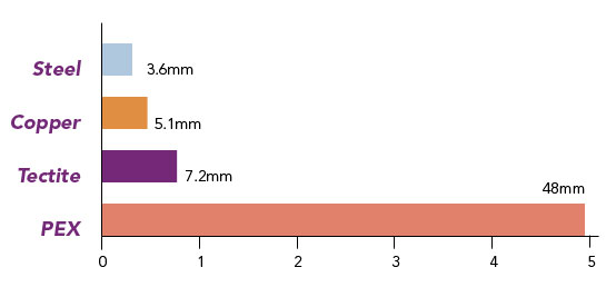
That is why you always have to take length differences into account as a result of variations in temperature. The temperature difference and the length of the pipe are the two parameters that will determine the change in length.
You can use the expansion table below to see the change in length that can be expected with a certain pipe length and a certain temperature difference. The coefficient of expansion is the same for both diameters.
| Expansion (mm/m) | Temperature difference (AT) | |||||||
|---|---|---|---|---|---|---|---|---|
| Pipe length (m) | 10°C | 20°C | 30°C | 40°C | 50°C | 60°C | 70°C | 80°C |
| 1 | 0.25 | 0.50 | 0.75 | 1.00 | 1.25 | 1.50 | 1.75 | 2.00 |
| 2 | 0.50 | 1.00 | 1.50 | 2.00 | 2.50 | 3.00 | 3.50 | 4.00 |
| 3 | 0.75 | 1.50 | 2.25 | 3.00 | 3.75 | 4.50 | 5.25 | 6.00 |
| 4 | 1.00 | 2.00 | 3.00 | 4.00 | 5.00 | 6.00 | 7.00 | 8.00 |
| 5 | 1.25 | 2.50 | 3.75 | 5.00 | 6.25 | 7.50 | 8.75 | 10.00 |
| 6 | 1.50 | 3.00 | 4.50 | 6.00 | 7.50 | 9.00 | 10.50 | 12.00 |
| 7 | 1.75 | 3.50 | 5.25 | 7.00 | 8.75 | 10.50 | 12.25 | 14.00 |
| 8 | 2.00 | 4.00 | 6.00 | 8.00 | 10.00 | 12.00 | 14.00 | 16.00 |
| 9 | 2.25 | 4.50 | 6.75 | 9.00 | 11.25 | 13.50 | 15.75 | 18.00 |
| 10 | 2.50 | 5.00 | 7.50 | 10.00 | 12.50 | 15.00 | 17.50 | 20.00 |
If system expansion is a concern there are a number of techniques which can reduce stress on tube and joints;
Always ensure the spur used to anchor the branch of a tee or connecting a radiator is long enough to allow normal thermal movement. Failure to observe this simple rule can lead to a failure. Incorporating expansion loops or bellows devices into the system can help guard against such problems.
The tube and fittings should be transported and stored with care in the original manufacturer’s packing. This protects all components against contamination and Tube against UV light.
Tube
The packaging should be carefully removed so that the Tube does not become damaged. Tectite recommends using the SAFECUT for this. Pipes should be unrolled in the opposite direction to which they were rolled, start with the pipe end on the outside of the coil.
TectSEAL™ 3PS
The TectSEAL™ 3PS is packaged to protect against contamination and retain the components integrity. The duel packs should be carefully opened immediately prior to insertion and placed directly into the calibrated tube end.
Fittings
As with the TectSeal 3PS, fittings bags should only be opened immediately prior to installation, this ensures the fitting avoids contamination and is less likely to be damaged.
- Cut the Tectite Tube with a hand tool. Use good quality cutters, ensure the blade is sharp and the cut is square. Make sure the Tube is clean and free from damage.
- Use the Tectite Calibrating Tools to provide a clean, square pipe end with chamfered edges. Calibration re-rounds the tube after cutting to prepare it for the TectSEALTM and for Push Fit jointing
- Push the TectSEAL 3PS into the Tube until the flange meets the tube end. TectSEALTM 3PS are pre-lubricated. Make sure all swarf is removed from the tube before fitting TectSEAL.
- Mark the insertion depth clearly on the Tube. Using a line and a V aids visibility after insertion. Tectite Calibration tools and Tectite Debur, Mark and Scribe tools can also help with insertion depth marking
- Push the Tube firmly into the fitting until the insertion depth mark reaches the demounting collar. Pushing with a twist will ease insertion
- Pull back on the pipe to check the joint is secure. Tectite fittings allow the Tube to rotate after jointing
Demounting video (can we switch the current video for a brass version rather than 316?)
- Select either the plastic clip or metal forks and apply to the fitting. The clip simply slides up to the fitting and locates the collar. The forks are placed with one arm on the body of the fitting, the second arm on the pipe against the collar.
- Separate and inspect Squeeze the disconnecting tool with one hand until the release collar in the fitting is depressed. With the other hand, twist out the tube/pipe using the thumb as a lever against the tool to assist disconnection. Check the fitting and tube/pipe for damage before remaking the joint.
NOTE: TectSEAL 3PS liners will remain in the fitting following demounting. This fitting can still be used again with Tectite Tube, gently insert again with a twist, observing the depth indicator.
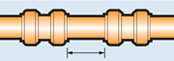
In order to ensure demounting is possible Observe minimum gaps and insertion distances to allow sufficient access for a demounting clip/tool.
| Fitting spacing for Tectite Classic, Pro and 316 | ||
|---|---|---|
| Sizes | Min. gap between fittings | Min. tube projection |
| 10mm | 10mm | 40mm |
| 12mm | 10mm | 40mm |
| 15mm | 10mm | 40mm |
| 22mm | 10mm | 50mm |
| 28mm | 10mm | 100mm |
| 35mm | 10mm | 100mm |
| 42mm | 10mm | 100mm |
| 54mm | 10mm | 100mm |
|
|

|
|---|---|---|
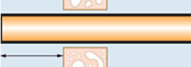
| Fitting spacing | Minimum projection | Good practice |
| Sufficient space must be left between fittings to allow room for dis-assembly tools to operate. See adjacent table for fitting spacing. | Similar consideration should be given to the distance pipe stubs project through walls or bulkheads. Refer to table. | Projection distances shown in the table also ensure that the subsequent installation will be a convenient distance from the wall. |
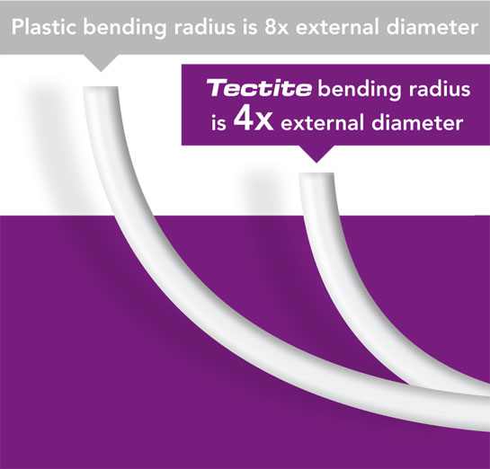
Tectite Tube can be bent manually without the aid of tools however, to achieve the tightest bend radius possible Tectite bending springs should be used. Tectite bending springs will enable bend a radius 4 x the outer diameter of the tube.
Specific clips are not required as the external diameter of Tectite tube is consistent with 15mm and 22mm clips readily available.
Please see the table below for guidance on clip distances for 15 and 22mm tube.
| Maximum spacing of support brackets for internal fixing of Tectite Tube and Copper | ||||
|---|---|---|---|---|
| Horizontal run spacing | Vertical run spacing | |||
| Copper tube to BS EN 1057 | R220 | R250/R290 | R220 | R250/R290 |
| 15mm | 1800mm | 1200mm | 2400mm | 1800mm |
| 22mm | 2400mm | 1800mm | 3000mm | 2400mm |